Private IP Configuration
A Guide for Dataflow Pipeline Execution
Goals
In this document, we’ll describe how to use Private IP for the execution of a dataflow pipeline.
Background
When we are running the dataflow pipeline, GCP decides to spawn one or more new VM-instances. By default, each VM-instance will have an External IP address.

Considering a billing account has a limited number of External IP addresses, we can skip this overhead by providing VPC-parameters as CLI-input of dataflow.
Following table* summarizes the required input parameters.
Field |
Description |
|---|---|
network |
The Compute Engine network for launching Compute Engine instances to run your pipeline. If not set, Google Cloud assumes that you intend to use a network named default. |
subnetwork |
The Compute Engine subnetwork for launching Compute Engine instances to run your pipeline. |
no_use_public_ips |
Command-line flag that sets use_public_ips to False. If the option is not explicitly enabled or disabled, the Dataflow workers use public IP addresses. |
(* excerpt from GCP pipeline-options)
Steps to Configure VPC
Configure VPC-Network & Subnetwork
Configure Firewall-Rule
Configure NAT & Router
Sample commands to trigger dataflow pipeline execution using above options
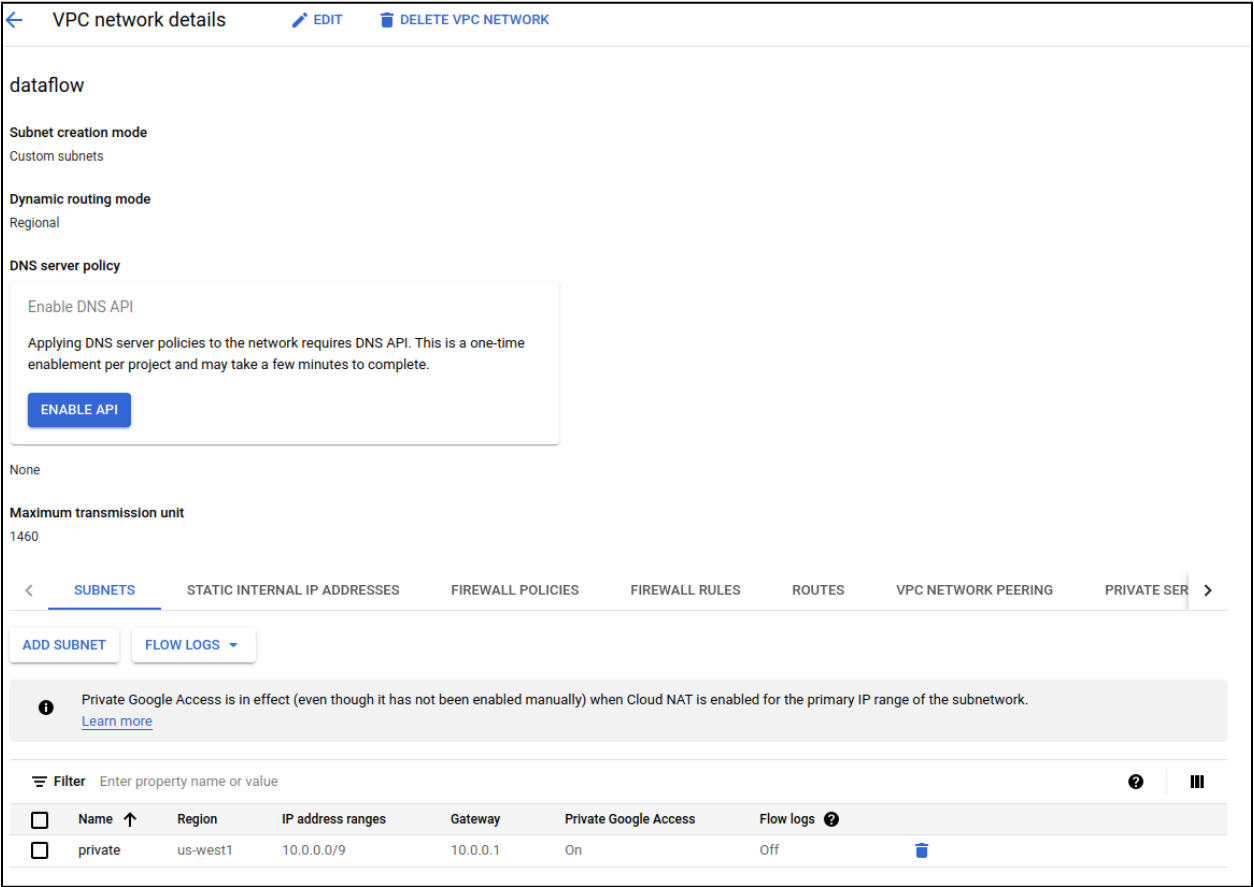
Configure VPC-Network & Subnetwork
Open GCP’s Create VPC-Network page.
Provide name, description.
Select “Subnet creation mode” as Custom.
Provide name, description, region, IP address range & other
Select “Private Google Access” as On.
Complete VPC-Network creation by providing other required parameters. Refer to GCP’s Create-VPC-Network documentation for more details.
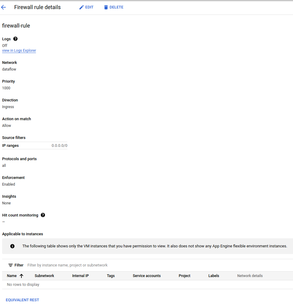
Configure Firewall-Rule
Open GCP’s Create a firewall rule page.
Provide name, description. You may set “Logs” as Off.
For the “Network” drop-down, select the network that we created in the previous step.
Select “Direction of traffic” as Ingress & “Action on match” as Allow.
Complete Firewall-Rule creation by providing other necessary information. Refer to GCP’s Configuring-Firewall documentation for more details.
Configure NAT & Router
Open GCP’s Create a NAT gateway page.
Provide name, region.
For the “Network” drop-down, select the network that we created earlier.
For the “Router” drop-down, EITHER select pre-created router OR click on “create new router”.
a. Complete router creation by providing name, description & region. Refer to GCP’s Create-Router documentation for more details.Complete NAT gateway creation by providing required details. Refer to GCP’s Create-NAT-Gateway documentation for more details.


Sample commands to trigger dataflow pipeline execution using above options
Following section showcases how VPC-parameters can be given as CLI inputs to weather-mv dataflow pipeline.
weather-mv --uris "gs://$STORAGE_BUCKET/*.nc"
           --output_table "$HOST_PROJECT_ID.$DATASET_ID.$TABLE_ID"
           --temp_location "gs://$STORAGE_BUCKET/tmp"
           --runner DataflowRunner
           --project $HOST_PROJECT_ID
           --region $REGION_NAME
           --no_use_public_ips
           --network=$NETWORK_NAME
           --subnetwork=regions/$REGION_NAME/subnetworks/$SUBNETWORK_NAME
Replace the following:
STORAGE_BUCKET: the storage bucket, e.g. bucket_58231
HOST_PROJECT_ID: the host project ID, e.g. weather_tools
DATASET_ID: the name of dataset, e.g. weather_mv_ds
TABLE_ID: the name of table, e.g. tbl_2017_01
REGION_NAME: the regional endpoint of your Dataflow job, e.g. us-central1
NETWORK_NAME: the name of your Compute Engine network, e.g. dataflow
Provide network_name same as what we created in Step-1.
SUBNETWORK_NAME: the name of your Compute Engine subnetwork, e.g. private
Provide a subnetwork_name same as what we created in Step-1.
Alternatively, you may also execute following command,
weather-mv --uris "gs://$STORAGE_BUCKET/*.nc"
           --output_table "$HOST_PROJECT_ID.$DATASET_ID.$TABLE_ID"
           --temp_location "gs://$STORAGE_BUCKET/tmp"
           --runner DataflowRunner
           --project $HOST_PROJECT_ID
           --region $REGION_NAME
           --no_use_public_ips
           –-subnetwork=https://www.googleapis.com/compute/v1/projects/$HOST_PROJECT_ID/regions/$REGION_NAME/subnetworks/$SUBNETWORK_NAME